H-Plane Bend
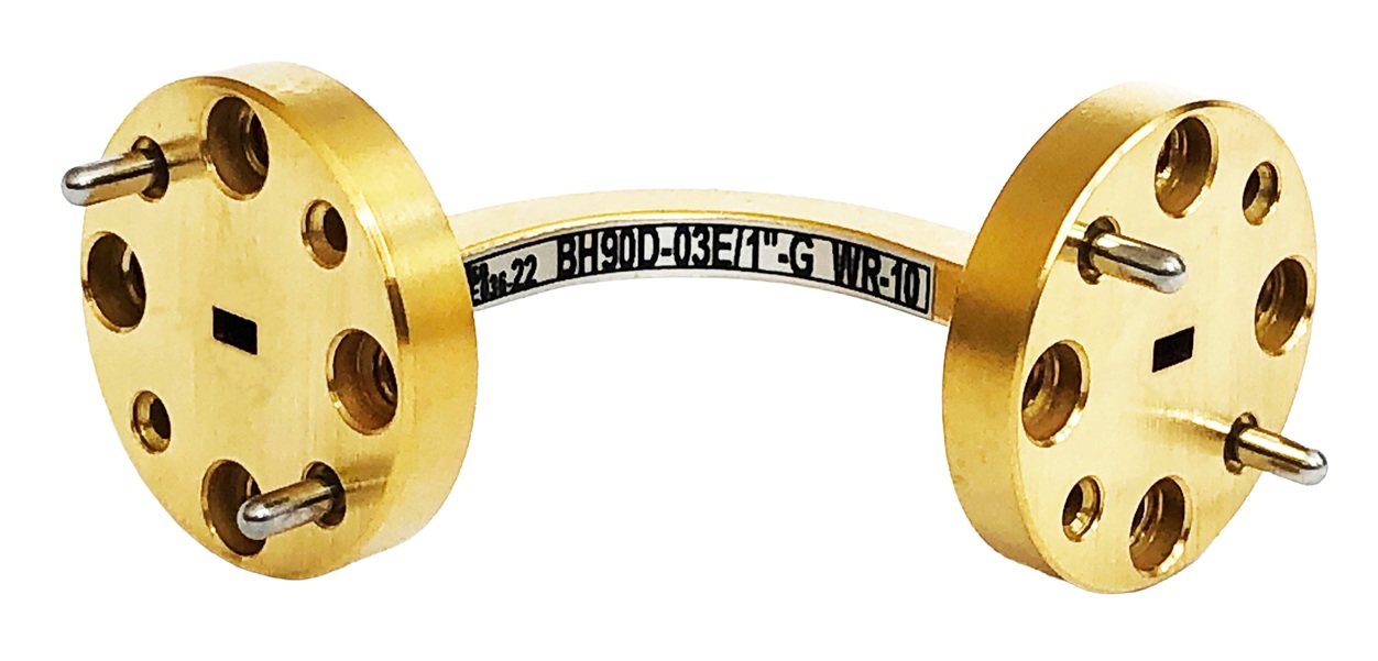
Flanged waveguide tube
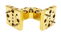
Split-block
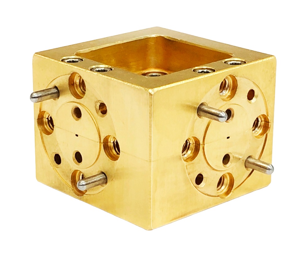
Split-block Cube
- Low insertion losses
- Precision flanges
- Low VSWR
H-Plane Bends are essential parts of every waveguide systems. H-Plane formed bends are available with angles of 15°, 30°, 45°, 90°. Maximum VSWR is 1.1. The sizes and combinations are available on request.
| Model | Frequency range, GHz | Waveguide size | VSWR |
| BH90-06E | 33 - 50 | WR-22 | 1.1 |
| BH90-04E | 50 - 75 | WR-15 | 1.1 |
| BH90-03E | 75 - 110 | WR-10 | 1.1 |
| BH90-02E | 110 - 170 | WR-6.5 | 1.1 |
| BH90-015E | 140 - 220 | WR-5.1 | 1.15 |
| BH90-012E | 170 - 260 | WR-4.3 | 1.15 |
| BH90-010E | 220 - 325 | WR-3.4 | 1.2 |
| BH90-008E/SB | 260 - 400 | WR-2.8 | 1.3 |
| BH90-006E/SB | 325 - 500 | WR-2.2 | 1.3 |
Ordering information
B Waveguide bend
E E-plane bend
H H-plane bend
A Angle
90°, 45°, 30°, 15°, (and other).
XX Operation range wave length, mm
L Arms length, (mm)
D Design type: Flanged waveguide tube, SB - Split-block, C- Split-block Cube 15x15mm
F Finish (flanges):
S - silver,
G - gold
BHA-XXE/D - L - F
Example: BH90-06E - 50 - S
H-Plane Bend, 90° bend angle, 33 - 50 GHz frequency range, flanged waveguide tube, 50mm length, silver plated.